Storage technology is the collection of hardware, protocols, data models and distributed systems used to preserve data and make it available to applications. It ranges from memory and local disks inside one computer to geographically distributed cloud object stores holding exabytes of data.
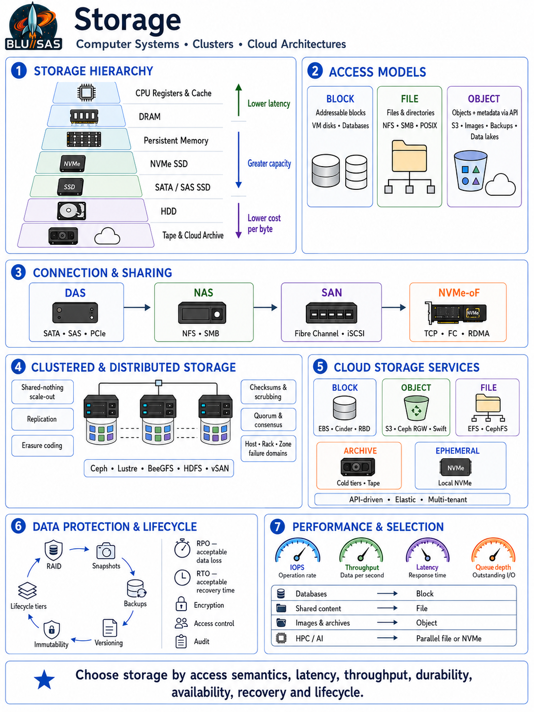
The most important distinction is how storage is presented to applications:
| Storage model | Application sees | Common uses |
|---|---|---|
| Block storage | Fixed-size addressable blocks | Operating systems, databases, virtual-machine disks |
| File storage | Files and directories | Shared documents, home directories, application content |
| Object storage | Objects addressed through an API | Images, videos, backups, archives, data lakes |
| Database storage | Records, rows, documents or key-value pairs | Transactional and analytical applications |
| Memory storage | Directly addressable volatile or persistent memory | Caches, high-speed databases, HPC workloads |
1. Storage inside a computer system
A computer uses a hierarchy of storage technologies. Capacity generally increases as data moves down the hierarchy, while latency and cost per byte decrease.
| Layer | Typical latency | Persistence | Role |
|---|---|---|---|
| CPU registers | Less than 1 ns | Volatile | Immediate CPU operations |
| CPU cache | About 1–30 ns | Volatile | Frequently accessed instructions and data |
| DRAM | About 50–150 ns | Volatile | Active application memory |
| Persistent memory/NVRAM | Sub-microsecond to several µs | Persistent | Fast durable data or memory extension |
| NVMe SSD | Tens to hundreds of µs | Persistent | High-performance local storage |
| SATA/SAS SSD | Hundreds of µs | Persistent | General-purpose storage |
| HDD | Several milliseconds | Persistent | Economical bulk capacity |
| Tape | Seconds to minutes for access | Persistent | Long-term offline archive |
| Remote/cloud storage | Sub-ms to hundreds of ms | Persistent | Shared and distributed storage |
Hard disk drives
A hard disk drive stores data magnetically on rotating platters. An actuator moves read/write heads to the required track.
Important HDD characteristics include:
- Rotational speed, commonly 7,200, 10,000 or 15,000 RPM.
- Seek latency—the time required to position the head.
- Rotational latency—the wait for the required sector to rotate under the head.
- Sequential throughput, typically much higher than random-I/O performance.
- IOPS, often only around 100–250 random operations per second for one drive.
HDDs remain useful for inexpensive, high-capacity storage, backup repositories, media archives and capacity-oriented distributed-storage tiers.
Solid-state drives
SSDs use NAND flash rather than moving mechanical components. They have far lower random-access latency and much higher IOPS than HDDs.
NAND cells may hold different numbers of bits:
| NAND type | Bits per cell | General characteristic |
|---|---|---|
| SLC | 1 | Fastest and most durable, but expensive |
| MLC | 2 | High endurance |
| TLC | 3 | Common enterprise and consumer balance |
| QLC | 4 | Higher density, lower write endurance |
| PLC | 5 | Very high density, with greater performance/endurance trade-offs |
An SSD contains a flash translation layer that maps logical block addresses to physical flash pages. It also performs:
- Wear levelling.
- Garbage collection.
- Bad-block management.
- Error correction.
- Write caching.
- TRIM/deallocation processing.
- Over-provisioning.
Because flash pages cannot normally be overwritten directly, old pages are invalidated and new versions written elsewhere. Entire erase blocks must eventually be reclaimed. This creates write amplification: the SSD may perform more physical writes than the host requested.
Enterprise SSDs may include power-loss protection, greater endurance, dual-port connectivity and more predictable latency.
SATA, SAS and NVMe
These technologies define how drives communicate with a host.
SATA
SATA evolved from consumer and desktop storage. It is inexpensive and commonly used for HDDs and general-purpose SSDs. SATA devices normally use the AHCI command interface, which was designed for rotating disks and supports relatively shallow command queues.
SAS
Serial Attached SCSI is widely used in enterprise servers and disk arrays. It supports:
- Dual-port drives.
- Multipath access.
- Large device topologies through SAS expanders.
- Enterprise error reporting.
- Higher availability than typical SATA configurations.
NVMe
NVMe is designed specifically for non-volatile memory connected through PCIe. It supports many queues with thousands of outstanding commands per queue, reducing lock contention and protocol overhead.
NVMe devices may appear as:
- PCIe add-in cards.
- U.2/U.3 drives.
- M.2 modules.
- EDSFF enterprise devices.
- NVMe namespaces carved from a physical device.
NVMe over Fabrics extends the NVMe protocol across a network using transports such as:
- NVMe/TCP.
- NVMe over Fibre Channel.
- NVMe/RDMA over RoCE or InfiniBand.
2. Local block-storage organisation
An operating system normally sees a disk as a sequence of logical block addresses.
flowchart TD
    A["Application"] --> B["File system or database"]
    B --> C["Logical volume or partition"]
    C --> D["Operating-system block layer"]
    D --> E["Device driver"]
    E --> F["SSD, HDD or storage controller"]
Partitions and volume managers
A partition table divides a disk into regions. Common formats include GPT and the older MBR scheme.
A logical volume manager introduces a flexible abstraction:
- Physical volumes provide raw capacity.
- Volume groups pool physical volumes.
- Logical volumes allocate capacity from the pool.
- Volumes can be extended, moved, mirrored or snapshotted.
Linux commonly uses LVM. Storage appliances may employ their own volume-management systems.
RAID
RAID combines multiple drives for performance, capacity, availability or some combination of these.
| RAID level | Method | Minimum drives | Failure tolerance |
|---|---|---|---|
| RAID 0 | Striping | 2 | None |
| RAID 1 | Mirroring | 2 | One drive per mirror |
| RAID 5 | Single distributed parity | 3 | One drive |
| RAID 6 | Dual distributed parity | 4 | Two drives |
| RAID 10 | Striped mirrors | 4 | Depends on which drives fail |
RAID is not a backup. It protects against certain device failures but not accidental deletion, corruption, malware, controller failure or site loss.
Large-capacity HDD arrays make rebuild time important. During a rebuild, remaining drives are heavily exercised and the array may be exposed to another failure. RAID 6, erasure coding or replicated distributed storage is therefore often preferred over RAID 5 for large arrays.
File systems
A file system translates filenames and directories into block allocations and metadata.
Typical responsibilities include:
- Directory and namespace management.
- Space allocation.
- File permissions and ownership.
- Timestamps and extended attributes.
- Crash recovery.
- Checksumming or journalling.
- Quotas.
- Snapshots and compression.
Common examples include:
- ext4: general-purpose Linux file system.
- XFS: scalable Linux file system suited to large files and parallel workloads.
- NTFS: principal Windows file system.
- APFS: Apple’s copy-on-write file system.
- ZFS: combined volume manager and copy-on-write file system.
- Btrfs: Linux copy-on-write file system with snapshots and checksums.
Journalling
A journalling file system records intended metadata changes before committing them. After a crash, the journal can be replayed instead of checking the entire file system.
Copy-on-write
In a copy-on-write system, updated data is written to a new location rather than overwriting the original block. Metadata is then switched to reference the new version.
This enables efficient:
- Snapshots.
- Clones.
- Rollback.
- Checksumming.
- Consistent point-in-time views.
Copy-on-write can also cause fragmentation and write amplification, especially for overwrite-heavy workloads.
3. Storage networking
Shared storage separates compute systems from the physical media. Servers access storage over a network or dedicated fabric.
Direct-attached storage
Direct-attached storage, or DAS, is connected to one server through SATA, SAS, PCIe or USB.
Advantages:
- Simple architecture.
- Low latency.
- No storage-network dependency.
- Good performance per cost.
Limitations:
- Capacity can be trapped within one server.
- Sharing requires a higher-level distributed service.
- Hardware failure may make the storage inaccessible.
- Operational scaling becomes difficult.
Storage area networks
A SAN presents remote storage as block devices. To the server, a SAN logical unit normally resembles a local disk.
SAN technologies include:
- Fibre Channel.
- iSCSI over TCP/IP.
- Fibre Channel over Ethernet.
- NVMe over Fabrics.
A SAN normally contains:
- Storage controllers.
- Disk or flash shelves.
- Logical unit numbers, or LUNs.
- Fibre Channel switches or Ethernet switches.
- Host bus adapters or network adapters.
- Multipathing software.
Multipathing provides several network paths between a host and a storage system. It can fail over around link, switch or controller failures and may distribute I/O across active paths.
SAN storage works well for databases, virtualisation platforms and applications requiring raw block devices. However, multiple servers cannot safely mount an ordinary local file system on the same LUN unless a cluster-aware file system or coordination layer is used.
Network-attached storage
NAS presents files rather than blocks.
Common protocols include:
- NFS for Unix and Linux systems.
- SMB for Windows and cross-platform file sharing.
- Parallel file-system client protocols for HPC environments.
The NAS server manages the file system and arbitrates concurrent access. Clients send operations such as open, read, write, rename and delete.
NAS is suitable for:
- Shared user directories.
- Application content.
- Departmental file shares.
- Build environments.
- Media workflows.
- Some container persistent-volume workloads.
4. Storage in clusters
A cluster requires storage that remains available when individual machines fail. This usually means distributing data, metadata and control functions across multiple nodes.
flowchart TD
    A["Applications and clients"] --> B["Storage protocol or API"]
    B --> C["Distributed metadata and placement"]
    C --> D["Storage node A"]
    C --> E["Storage node B"]
    C --> F["Storage node C"]
    D --> G["Replication or erasure coding"]
    E --> G
    F --> G
Shared-disk and shared-nothing architectures
Shared-disk
Several compute nodes access the same underlying storage array. Coordination is provided by a cluster file system, distributed lock manager or database clustering layer.
Benefits include centralised data management and simple movement of workloads between compute nodes. The shared array, however, must itself be highly available.
Shared-nothing
Each node owns local storage, and the storage software distributes data among nodes. There is no single shared disk subsystem.
Examples include Ceph, Cassandra, HDFS, MinIO and many cloud object stores.
This approach:
- Scales capacity and bandwidth by adding nodes.
- Can tolerate node and rack failures.
- Avoids dependence on a single large storage array.
- Requires distributed placement, recovery and consistency mechanisms.
Distributed file systems
A distributed file system provides a shared file namespace across many storage servers.
Examples include:
- CephFS.
- Lustre.
- IBM Storage Scale, formerly GPFS.
- GlusterFS.
- HDFS.
- BeeGFS.
- Amazon EFS and Google Filestore as managed services.
Different systems optimise for different workloads.
Lustre and BeeGFS target high-throughput HPC workloads. HDFS targets large sequential data processing. CephFS provides a general POSIX-compatible namespace backed by Ceph’s distributed object layer.
A distributed file system often separates:
- Metadata operations, such as directory lookup and permissions.
- Data operations, such as reading and writing file extents.
- Cluster management and failure detection.
Metadata can become a scaling bottleneck when a workload creates or scans millions of small files.
Parallel file systems
A parallel file system allows clients to perform I/O against multiple storage servers simultaneously.
For example, a large file may be striped across several object-storage targets. A compute node can then read different parts concurrently, achieving aggregate throughput beyond that of a single server or disk.
Parallel file systems are important in:
- Supercomputing.
- AI model training.
- Scientific simulation.
- Genomics.
- Large-scale media processing.
Their design often prioritises bandwidth and metadata scalability over internet-facing access or low-cost archival retention.
Distributed block storage
Distributed block systems provide virtual disks backed by storage spread across a cluster.
Examples include:
- Ceph RADOS Block Device.
- Longhorn.
- LINSTOR with DRBD.
- VMware vSAN.
- Amazon EBS as a managed cloud service.
A virtual block device is divided into extents or objects. Those units are replicated or erasure-coded across storage nodes. The client or storage gateway translates block I/O into distributed operations.
Distributed block storage is commonly used for:
- Virtual-machine boot and data volumes.
- Kubernetes persistent volumes.
- Databases.
- Stateful services requiring file systems.
5. Object storage
Object storage manages data as objects rather than mounted files or addressable disk blocks.
An object normally contains:
- A unique key or name.
- The data payload.
- System metadata.
- User-defined metadata or tags.
- An identifier such as a checksum, version ID or entity tag.
Objects are stored in buckets or containers and accessed through HTTP APIs. Amazon S3 established the most widely adopted object-storage API model.
Typical operations include:
PUTan object.GETan object.HEADits metadata.DELETEan object.- List objects by key prefix.
- Add tags or metadata.
- Create pre-signed time-limited URLs.
- Retrieve a particular object version.
Why object storage scales effectively
Object storage avoids maintaining a conventional global directory tree with complex POSIX locking semantics. Keys can be mapped algorithmically across a large population of storage devices.
The system can distribute objects by:
- Hashing the object identifier.
- Consulting a placement map.
- Applying failure-domain rules.
- Selecting replica or erasure-code locations.
This makes object storage well suited to billions or trillions of relatively immutable items.
Typical uses include:
- Image and video archives.
- Backups.
- Software artefacts.
- Machine images.
- Logs and telemetry.
- Data lakes.
- Static website assets.
- AI training datasets.
It is usually less suitable as a direct replacement for a low-latency transactional database disk because object updates and small random writes have different semantics and higher latency than block storage.
S3 concepts
An S3-compatible system generally supports:
- Buckets and object keys.
- Multipart upload for large objects.
- Versioning.
- Object tags and metadata.
- Server-side encryption.
- Lifecycle policies.
- Retention and object locking.
- Replication.
- Access policies.
- Event notifications.
- Checksums.
- Storage classes.
S3-compatible implementations include Ceph Object Gateway, MinIO and numerous cloud or appliance products. Compatibility is not always identical: authentication, object-locking behaviour, lifecycle rules and advanced APIs should be tested against the intended client software.
6. Data protection mechanisms
Replication
Replication stores multiple complete copies of the data.
With three-way replication, one unit of user data consumes approximately three units of raw capacity, excluding metadata and operational reserves.
Advantages:
- Simple recovery model.
- Fast reads from alternative replicas.
- Good performance for small objects or writes.
- Failure recovery is relatively straightforward.
Disadvantages:
- High capacity overhead.
- Cross-region replication can be expensive.
- Synchronous replication increases write latency.
Erasure coding
Erasure coding divides data into data fragments and calculates parity fragments. A configuration described as k+m has:
- k data fragments.
- m parity fragments.
- k+m total fragments.
For example, a 4+2 scheme creates four data fragments and two parity fragments. Any four surviving fragments can reconstruct the original data.
Its raw capacity overhead is:Overhead=kk+m
For 4+2:46=1.5
This means 1 TB of logical data consumes approximately 1.5 TB before metadata and operational reserve, rather than 3 TB with three-way replication.
Erasure coding is efficient for large, relatively stable data, but it introduces:
- CPU cost for encoding and reconstruction.
- More network operations.
- Higher small-write overhead.
- More complex recovery behaviour.
Checksums and scrubbing
Checksums detect corruption that hardware may not report. End-to-end checksum protection can verify data when it is written, transmitted, stored and read.
Background scrubbing periodically reads stored data, validates checksums and repairs damaged copies using valid replicas or erasure-code fragments.
This protects against silent corruption or bit rot, which RAID alone may not reliably identify.
Snapshots
A snapshot records the state of a volume or file system at a particular time. Copy-on-write snapshots initially consume little capacity, but their storage use grows as data changes.
Snapshots are valuable for:
- Fast recovery from mistakes.
- Consistent backups.
- Test-environment cloning.
- Database protection when coordinated with the database.
Snapshots stored on the same system are not independent backups. Failure or compromise of the source storage may destroy both the active data and its snapshots.
Backup
A robust backup design commonly follows the 3-2-1 principle:
- Three copies of the data.
- Two different media or storage systems.
- One copy off-site.
Modern extensions recommend an immutable or offline copy and regular recovery verification.
Backups must be evaluated by:
- Recovery point objective: how much recent data may be lost.
- Recovery time objective: how quickly service must be restored.
- Retention period.
- Restore granularity.
- Immutability.
- Encryption.
- Geographic separation.
- Tested recoverability.
7. Consistency and distributed-systems behaviour
Distributed storage must decide when a write is considered successful and what later readers are guaranteed to observe.
Strong consistency
After a successful write, subsequent reads return the new value. This is easier for applications but requires coordination among nodes.
Eventual consistency
Replicas may temporarily return different values, but converge if no further updates occur. This can improve availability or geographic performance but requires applications to tolerate stale reads.
Modern systems frequently offer more nuanced guarantees:
- Read-after-write consistency.
- Strong consistency for an individual object.
- Eventual consistency for listings or secondary indexes.
- Tunable consistency based on read and write quorum sizes.
Quorums
Suppose data is stored on N replicas:
- A write must be acknowledged by W replicas.
- A read consults R replicas.
When:R+W>N
the read and write sets overlap, which can help provide consistent reads, subject to the system’s conflict-resolution model.
CAP considerations
During a network partition, a distributed system must generally choose between:
- Consistency: reject or delay operations that cannot be safely coordinated.
- Availability: continue serving operations even if different partitions temporarily diverge.
CAP does not mean a system permanently chooses only two of three qualities. It describes behaviour specifically when a network partition occurs.
Split brain and fencing
A split-brain condition occurs when isolated parts of a cluster each believe they are authoritative. If both accept conflicting writes, data can be corrupted.
Clusters control this using:
- Quorum voting.
- Consensus protocols such as Raft or Paxos.
- Leases.
- Distributed locks.
- Fencing or STONITH, which forcibly prevents an unhealthy node from accessing shared storage.
- Epochs or generation numbers.
8. Storage in virtualised systems
A virtual machine normally sees a virtual block device. The underlying data may reside on:
- A host-local file.
- A logical volume.
- A SAN LUN.
- A Ceph RBD image.
- A cloud block-storage volume.
- An object-backed image service.
The I/O path can contain several layers:
flowchart TD
    A["Guest application"] --> B["Guest file system"]
    B --> C["Virtual disk driver"]
    C --> D["Hypervisor or paravirtual I/O"]
    D --> E["Host or distributed block layer"]
    E --> F["Physical storage devices"]
Each layer can introduce caching, queuing, checksumming and write-ordering behaviour. Correct handling of flush and barrier operations is essential. A database may believe a transaction is durable after issuing a flush; every layer must honour that request before acknowledging completion.
Thin provisioning lets a virtual disk advertise more capacity than has physically been allocated. It improves utilisation but risks overcommitment if logical volumes grow faster than physical capacity.
Linked clones and copy-on-write backing images reduce the space and time needed to create virtual machines, although long chains can affect performance and complicate management.
9. Storage in cloud architecture
Cloud storage separates logical resources from their physical implementation and exposes them through APIs.
The principal cloud services are:
| Service | Resource exposed | Typical example |
|---|---|---|
| Block storage | Attach/detach virtual volume | Amazon EBS, OpenStack Cinder |
| Object storage | Bucket and objects | Amazon S3, Ceph RGW, OpenStack Swift |
| File storage | Managed shared file system | Amazon EFS, Azure Files |
| Archive storage | Low-cost delayed retrieval | S3 Glacier-class services |
| Ephemeral storage | Compute-local temporary disk | Instance store or local NVMe |
| Database storage | Managed database abstraction | Relational, document or key-value service |
Cloud block storage
A cloud block service creates volumes independently of virtual-machine lifecycles. A control plane manages:
- Volume creation.
- Attachment and detachment.
- Snapshots.
- Cloning.
- Encryption keys.
- Capacity types and performance tiers.
- Availability-zone placement.
The data plane carries the actual reads and writes, using technologies such as iSCSI, Fibre Channel, NVMe-oF, network replication or distributed block storage.
In OpenStack, Cinder provides this abstraction through drivers for systems such as Ceph RBD, enterprise arrays and LVM-backed services.
Cloud image storage
Virtual-machine images are usually stored as immutable or mostly immutable artefacts. In OpenStack, Glance records image metadata and uses a backend such as:
- Ceph RBD.
- Swift.
- S3-compatible object storage.
- A file system.
- Another supported storage service.
When an instance is launched, the image may be copied, cloned or referenced through copy-on-write mechanisms.
For long-term image archiving, object storage is usually attractive because it provides large-scale capacity, metadata, versioning, checksums, lifecycle policies and immutability controls.
Availability zones and regions
Cloud storage is organised around failure domains:
- Device.
- Server.
- Chassis.
- Rack.
- Power or network zone.
- Availability zone.
- Region.
Data placement should ensure that replicas or erasure-code fragments do not share the same likely failure domain.
Synchronous replication is typically used within a region or availability domain when low data loss is required. Cross-region replication is often asynchronous because geographic latency makes synchronous writes expensive.
10. Ceph as a converged cluster-storage example
Ceph is a useful example because one storage cluster can provide block, file and object interfaces.
Its core components include:
- RADOS: the distributed object-storage foundation.
- OSDs: daemons that store data on individual devices.
- Monitors: maintain cluster maps and quorum.
- Managers: provide operational and monitoring services.
- CRUSH: calculates data placement across failure domains.
- RBD: distributed block devices.
- CephFS: shared file system.
- RGW: S3- and Swift-compatible object gateway.
flowchart TD
    A["Virtual machines: RBD"] --> D["Ceph RADOS"]
    B["Shared files: CephFS"] --> D
    C["S3 objects: RGW"] --> D
    D --> E["OSD nodes and storage devices"]
    D --> F["Replication or erasure coding"]
CRUSH allows clients to calculate where data should reside without relying on a central lookup table for every I/O operation. Placement rules can spread data across hosts, racks or other topology levels.
Ceph works particularly well when an organisation needs a scale-out, software-defined system serving several storage models. Its trade-offs are operational complexity, network demands, recovery traffic and the need for careful device and failure-domain design.
11. Container and Kubernetes storage
Containers have ephemeral writable layers by default. Persistent application data must be stored separately.
Kubernetes uses several abstractions:
- PersistentVolume: an available storage resource.
- PersistentVolumeClaim: a workload’s request for storage.
- StorageClass: describes provisioning and performance policy.
- Container Storage Interface: connects Kubernetes to storage providers.
- VolumeSnapshot: represents a point-in-time snapshot.
Access modes commonly include:
- ReadWriteOnce: generally mounted read-write by one node.
- ReadOnlyMany: mounted read-only by multiple nodes.
- ReadWriteMany: mounted read-write by multiple nodes.
- ReadWriteOncePod: exclusive to one pod.
A CSI driver may provision Ceph RBD volumes, CephFS shares, cloud block volumes, NFS exports or other storage.
Stateful Kubernetes workloads require attention to:
- Pod rescheduling.
- Volume-zone affinity.
- Attachment time.
- Backup consistency.
- Database replication.
- Storage latency.
- Failure recovery.
12. Storage performance
Storage performance cannot be described by one number.
IOPS
Input/output operations per second measures operation rate. It matters for small random-I/O workloads such as databases and VM farms.
Throughput
Throughput measures bytes transferred per second. It matters for large sequential operations such as media processing, backup, scientific data and model training.
Approximate relationship:Throughput=IOPS×Average I/O size
For example, 20,000 IOPS at 16 KiB per operation corresponds to roughly:20,000×16 KiB≈312.5 MiB/s
assuming the workload and system can sustain it.
Latency
Latency is the completion time of an individual operation. Average latency can conceal serious pauses, so systems should monitor percentiles such as p95, p99 and p99.9.
Storage latency includes:
- Application queuing.
- Operating-system processing.
- Network traversal.
- Controller queues.
- Media access.
- Replication acknowledgements.
- Checksumming or encryption.
- Recovery or garbage-collection activity.
Queue depth
Queue depth is the number of outstanding I/O requests. Increasing it can improve throughput through parallelism, but excessive queuing raises latency.
Workload patterns
Performance depends strongly on:
- Sequential versus random access.
- Read/write ratio.
- I/O size.
- Synchronous versus asynchronous writes.
- Number of clients.
- Working-set size.
- Compressibility.
- Deduplication rate.
- Metadata intensity.
- Small-file count.
- Locality and cache effectiveness.
A headline device benchmark rarely predicts application performance unless its workload resembles the intended production workload.
13. Caching and tiering
Caches reduce latency by keeping frequently accessed data in faster storage.
Common cache locations include:
- Application memory.
- Operating-system page cache.
- File-system cache.
- Database buffer pool.
- Storage-controller cache.
- SSD cache in front of HDDs.
- CDN edge cache in front of object storage.
Write policies include:
- Write-through: acknowledge after data reaches the lower persistent layer.
- Write-back: acknowledge after storing it in a faster cache, then destage later.
- Write-around: bypass the cache for some writes.
Write-back caching requires protected memory, replication or power-loss protection to avoid acknowledged writes being lost.
Storage tiering moves data according to access patterns:
- Hot tier: NVMe or high-performance SSD.
- Warm tier: general-purpose SSD or HDD.
- Cool tier: capacity HDD or low-cost object storage.
- Archive tier: tape or delayed-retrieval cloud storage.
Lifecycle policies can automate movement or deletion based on age, tags, version count or last-access information.
14. Security
Storage security should cover confidentiality, integrity, availability and controlled deletion.
Important controls include:
- Encryption in transit using TLS or storage-fabric security.
- Encryption at rest.
- Central key-management systems.
- Per-volume, per-object or tenant-specific keys.
- Authentication and role-based access control.
- Bucket policies and access-control lists.
- Network isolation.
- Audit logging.
- Immutable retention.
- Secure erase and cryptographic erasure.
- Tenant isolation.
- Malware and ransomware protection.
Client-side encryption protects data before it reaches the storage service, but it reduces the service’s ability to inspect, transform or search the content.
Object lock or write-once-read-many storage prevents deletion or alteration during a retention period. This is valuable for regulatory records, golden images and ransomware-resistant backups.
15. Capacity planning
Usable capacity is always lower than the installed raw capacity.
A simplified calculation is:Required raw capacity=Target utilisationLogical data×Protection overhead
If an archive needs 500 TB of logical data, uses 4+2 erasure coding and is limited to 80% utilisation:0.8500×1.5=937.5 TB
Additional allowance may be needed for:
- Metadata.
- Temporary recovery space.
- Snapshots and old versions.
- Growth during procurement.
- Filesystem reserve.
- Compression uncertainty.
- Failed or maintenance-mode devices.
- Rebalancing.
- Incomplete multipart uploads.
Distributed storage should not normally be run close to 100% capacity. Recovery and rebalancing require free space, and placement becomes increasingly constrained as the cluster fills.
16. Selecting the appropriate storage model
| Requirement | Usually favours |
|---|---|
| Database with small random writes | Local NVMe or high-performance block storage |
| Virtual-machine disks | Block storage |
| Shared departmental directories | NAS or distributed file storage |
| HPC parallel workload | Parallel file system |
| Kubernetes single-writer application | CSI-provisioned block volume |
| Kubernetes shared writable content | Distributed file storage |
| Images, videos and immutable artefacts | Object storage |
| Backups and long-term archive | Object storage or tape |
| Very low-latency temporary processing | Compute-local NVMe |
| Geographic distribution | Object storage or application-aware replication |
| Billions of independent items | Object storage |
| Full POSIX semantics | File storage |
| Direct sector-level access | Block storage |
In practice, mature architectures use several types together. A cloud application might use:
- NVMe for database caching.
- Block storage for database volumes.
- File storage for shared application data.
- Object storage for images, backups and logs.
- An archive tier for older object versions.
- A separate replicated backup system for disaster recovery.
The key is to select storage according to access semantics, latency, throughput, durability, availability, recovery objectives, security and lifecycle—not simply according to raw capacity or device speed.